English
  English
 русский
 日本語
日本語 Español
 中文简体
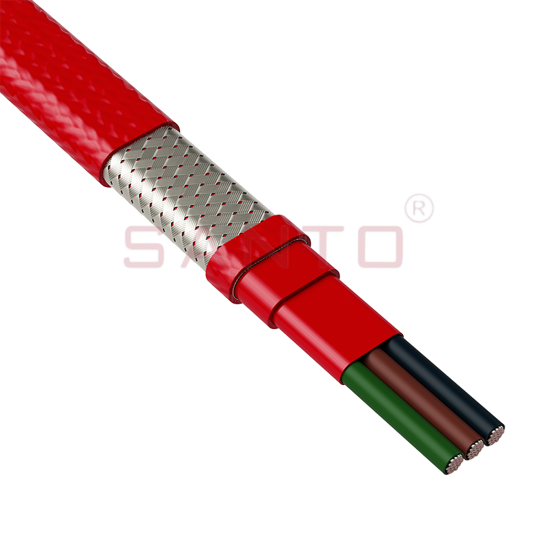
中文简体Floor heating wire is a resistive electric cable embedded beneath floor surfaces to generate radiant heat — and choosing the right type, wattage, and spacing is the single most important factor in achieving efficient, even warmth throughout your space. Whether you are retrofitting a cold bathroom, finishing a basement, or designing a whole-home radiant floor system, understanding how floor heating wire works, what specifications matter, and how installation decisions affect long-term performance will save you money and prevent costly mistakes. This guide covers every critical aspect from wire types and power density to spacing calculations, thermostat integration, and maintenance.
Content
- What Is Floor Heating Wire and How Does It Work?
- Types of Floor Heating Wire: Single-Conductor vs. Twin-Conductor
- Floor Heating Wire Power Output: Choosing the Right Wattage
- Floor Heating Wire Spacing: How to Lay It Correctly
- Compatible Floor Coverings: Which Floors Work Best with Heating Wire?
- Step-by-Step Floor Heating Wire Installation Overview
- Thermostat Options for Floor Heating Wire Systems
- Energy Costs: How Much Does Running Floor Heating Wire Cost?
- Frequently Asked Questions About Floor Heating Wire
- Q1: Can floor heating wire be cut to length on-site?
- Q2: How long does floor heating wire last?
- Q3: What is the difference between floor heating wire and a heating mat?
- Q4: How thick is floor heating wire, and will it raise my floor height significantly?
- Q5: Can I install floor heating wire under an existing tile floor?
- Q6: Is underfloor insulation necessary with floor heating wire?
- Conclusion: Selecting and Installing Floor Heating Wire the Right Way
What Is Floor Heating Wire and How Does It Work?
Floor heating wire works on the principle of electrical resistance heating: when current passes through a resistive conductor, the wire converts electrical energy into heat, which radiates upward through the floor covering to warm the room from the ground up. Unlike forced-air heating systems that heat the air (which then stratifies toward the ceiling), radiant floor heating warms objects and people directly, creating a more even and comfortable thermal environment.
A typical electric floor heating wire system consists of three main components: the heating cable itself, a thermostat with floor sensor, and the floor covering. The wire is laid in serpentine patterns across the subfloor or embedded in a thin-set mortar bed, then connected to a dedicated electrical circuit via the thermostat. When activated, the wire heats the floor mass, which then radiates heat into the room.
Most residential floor heating wire systems operate at standard household voltages — 120V in North America and 230V in Europe and most of the rest of the world. The wire's resistance per meter (or foot) determines how much heat it produces per unit length, which in turn dictates the correct spacing for a given power output per square meter.
Types of Floor Heating Wire: Single-Conductor vs. Twin-Conductor
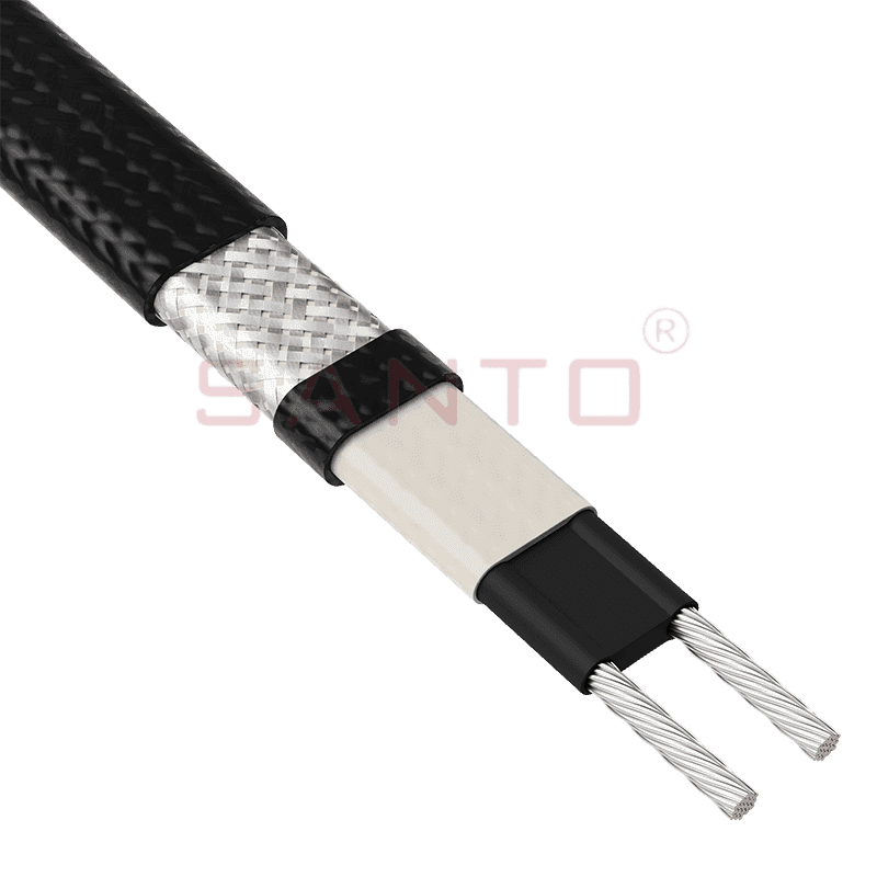
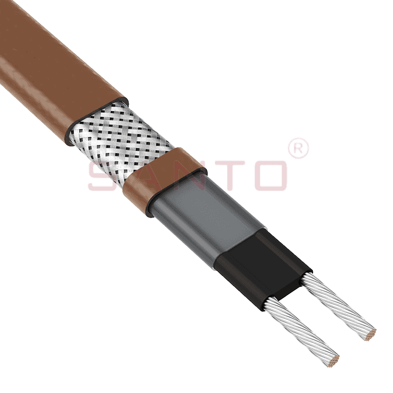
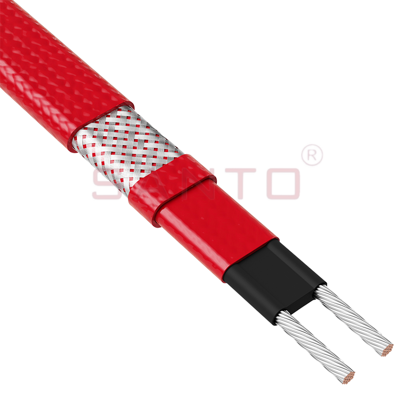
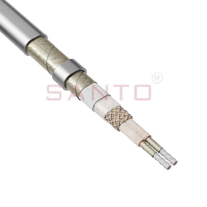
The two primary configurations of floor heating wire are single-conductor (single-core) and twin-conductor (twin-core) cables, and the choice between them affects installation flexibility, EMF emissions, and overall system complexity.
Single-Conductor Floor Heating Wire
Single-conductor floor heating wire requires both ends of the cable to be routed back to the thermostat connection point, which adds installation complexity but allows more flexible layout patterns. Because the circuit is formed between the two ends of a single wire, the installer must plan the routing carefully so both ends terminate at the same wall location. This wire type is typically less expensive per meter than twin-conductor alternatives and is well-suited for irregularly shaped rooms.
Twin-Conductor Floor Heating Wire
Twin-conductor floor heating wire contains two conductors running parallel within a single cable jacket, meaning only one end connects to the thermostat — the other end terminates freely within the floor with a factory-sealed end cap. This design dramatically simplifies installation, as the cable behaves like a one-ended wire: you route it in any pattern and the free end simply stops wherever the coverage area ends. Twin-conductor cables also produce a self-canceling electromagnetic field, resulting in significantly lower EMF emissions — typically less than 1 mG at floor level, compared to 3–8 mG for single-conductor systems.
| Feature | Single-Conductor Wire | Twin-Conductor Wire |
| Connection Points | Both ends at thermostat | One end at thermostat |
| EMF Emissions | Higher (3–8 mG) | Very low (<1 mG) |
| Installation Flexibility | High (irregular shapes) | Very High (simpler routing) |
| Cost per Meter | Lower | Slightly higher |
| Suitable for Bedrooms | With caution | Preferred |
| Free-End Termination | Not applicable | Factory-sealed end cap |
Table 1: Comparison of single-conductor and twin-conductor floor heating wire across key installation and performance parameters.
Floor Heating Wire Power Output: Choosing the Right Wattage
The power density of a floor heating wire system — measured in watts per square meter (W/m²) — is the single most important specification for comfort and energy efficiency, and getting it wrong results in either an under-heated floor or excessive energy waste.
As a general guideline, most residential floor heating wire installations target the following power densities based on room type and insulation quality:
- Bathroom / ensuite (primary heating): 150–180 W/m² — tile floors over a well-insulated slab typically require 150 W/m²; poorly insulated ground-floor slabs may need up to 200 W/m².
- Living room / bedroom (supplemental heating): 100–130 W/m² — when a central heating system handles most of the load, floor heating provides comfort warmth rather than primary heat.
- Kitchen (supplemental heating): 100–120 W/m² — account for the fact that cabinetry and appliances cover a significant portion of the floor area and should be excluded from the heated zone.
- Outdoor / snow-melt (driveways, steps): 300–500 W/m² — anti-icing applications require substantially higher power density to overcome heat loss to the outdoor environment.
- Concrete slab / screed embed (primary heating): 180–200 W/m² — thermal mass of concrete requires higher input to achieve comfortable surface temperatures within reasonable warm-up times.
How to Calculate Total Power Requirements
Total system wattage equals the heated floor area in square meters multiplied by the target power density in W/m², and this figure determines the required circuit breaker size and wire length.
Example: A 6 m² bathroom (excluding shower tray and vanity footprint, actual heated area = 4.5 m²) at 150 W/m² requires a total of 675 W. On a 230V system, this draws approximately 2.9 A — well within a standard 16A circuit. On a 120V system, the same 675 W draws 5.6 A, still safely within a 15A circuit.
Larger installations — such as a 40 m² open-plan living area at 120 W/m² = 4,800 W — require dedicated 20A or 30A circuits and may need to be split into multiple zones, each with its own thermostat, to stay within single-circuit wiring limits.
Floor Heating Wire Spacing: How to Lay It Correctly
Wire spacing — the center-to-center distance between parallel runs of floor heating wire — directly determines the power density delivered to the floor surface, and must be calculated precisely rather than estimated.
The correct spacing formula is:
Spacing (mm) = Wire Length (m) × 1000 ÷ Heated Area (m²) × 100
Or more directly: Spacing (cm) = 100 ÷ (W/m² ÷ Wire Wattage per Meter)
For a practical example: a twin-conductor heating cable rated at 17 W/m (a common specification) targeting 150 W/m² requires a spacing of: 17 ÷ 150 × 1000 = approximately 113 mm (11.3 cm) center-to-center. Most installation guidelines recommend rounding down to the nearest 5 mm for a conservative, slightly higher output, so 110 mm spacing would be used.
| Wire Output (W/m) | Target: 100 W/m² | Target: 150 W/m² | Target: 200 W/m² |
| 10 W/m | 100 mm | 67 mm | 50 mm |
| 17 W/m | 170 mm | 113 mm | 85 mm |
| 20 W/m | 200 mm | 133 mm | 100 mm |
| 25 W/m | 250 mm | 167 mm | 125 mm |
Table 2: Required floor heating wire spacing (center-to-center, in mm) for different wire output ratings and target power densities. Smaller spacing = higher heat output per m².
Never space floor heating wire closer than 50 mm — tighter spacing causes localized overheating that can damage wire insulation, crack tile grout, or in extreme cases cause a fire. Most manufacturers specify a minimum spacing of 60–80 mm regardless of calculated requirements.
Compatible Floor Coverings: Which Floors Work Best with Heating Wire?
Ceramic and porcelain tile are the most compatible and efficient floor coverings for use with electric floor heating wire, but engineered wood, laminate, luxury vinyl plank (LVP), and natural stone are also suitable with the correct installation method.
| Floor Covering | Compatibility | Max. Floor Temp. | Notes |
| Ceramic / Porcelain Tile | Excellent | No limit (practical 35°C) | Best thermal conductor |
| Natural Stone (Marble, Slate) | Excellent | 35°C max surface | Verify stone sensitivity |
| Engineered Hardwood | Good | 27°C max surface | Use low-power density |
| Laminate Flooring | Conditional | 27°C max surface | Must be rated "underfloor heating compatible" |
| Luxury Vinyl Plank (LVP) | Good | 27°C max surface | Check manufacturer approval |
| Solid Hardwood | Not recommended | N/A | Warps / cracks with heat cycling |
| Carpet | Not recommended | N/A | Insulates heat; overheating risk |
Table 3: Compatibility of common floor coverings with electric floor heating wire systems, including maximum recommended surface temperatures.
Step-by-Step Floor Heating Wire Installation Overview
A successful floor heating wire installation follows a strict sequence: room measurement and load calculation, circuit verification, wire layout planning, physical installation with securing clips, floor sensor placement, electrical connection to the thermostat, and a mandatory resistance test before covering.
Step 1 — Measure and Calculate
Measure the total room area, then subtract any fixed obstacles (toilets, vanity base, built-in cabinetry) to get the true heated floor area. Order wire length based on the calculated spacing: wire length = heated area ÷ spacing (in meters). Always order 5–10% extra length to account for routing around obstacles.
Step 2 — Verify Electrical Circuit
Confirm the existing circuit can handle the heating load, or have a licensed electrician install a dedicated circuit before beginning any work. Electric floor heating wire in wet areas (bathrooms, kitchens) must be protected by a GFCI/RCD breaker regardless of local code requirements — this is a non-negotiable safety requirement.
Step 3 — Record the Resistance Value
Before laying a single meter of wire, use a multimeter to measure and record the wire's initial resistance — this baseline value is essential for the post-installation verification test. Every roll of quality floor heating wire should include a label or documentation showing the rated resistance; if the measured value deviates by more than 5% from the rated value, the cable may be damaged.
Step 4 — Lay and Secure the Wire
Use manufacturer-supplied fixing tape or plastic staple clips to secure the wire at its calculated spacing, routing it in consistent parallel runs from one end of the room to the other. Never cross heating wires over each other — crossing causes localized hot spots that can overheat and damage insulation. Maintain at least 50–80 mm between parallel runs and at least 50 mm from walls.
Step 5 — Install the Floor Sensor
The floor temperature sensor must be placed between two parallel wire runs, equidistant from each, and housed in a conduit so it can be replaced without disturbing the floor covering. Position the sensor approximately 500–600 mm from the wall, centered in the heated zone. A sensor positioned directly over a wire will read excessively high temperatures, causing the thermostat to cycle off prematurely and reduce comfort.
Step 6 — Post-Installation Resistance Test
After embedding the wire in tile adhesive or self-leveling compound — but before the floor covering is laid — re-measure the wire resistance and confirm it matches the initial baseline value within ±5%. This test catches any damage to the wire caused during the tiling or screeding process. Skipping this test and discovering a damaged wire after the floor is finished can result in a complete floor demolition at significant cost.
Thermostat Options for Floor Heating Wire Systems
The thermostat is the control brain of any floor heating wire system, and upgrading from a basic manual thermostat to a programmable or smart model can reduce energy consumption by 25–40% without sacrificing comfort.
- Basic manual thermostat: Manual on/off with a dial temperature control. Lowest cost (typically $30–$60), simplest installation, but no scheduling capability. Energy-inefficient for primary heating applications.
- Programmable thermostat: Allows scheduling of heating periods by time and day of week. A 7-day programmable thermostat can reduce heating runtime by 30% in a typical bathroom application by activating the floor only during morning and evening usage windows. Cost: $60–$120.
- Smart Wi-Fi thermostat: App-controlled with geofencing, adaptive learning, and energy monitoring. Can integrate with smart home platforms. Best for large installations or whole-home radiant systems. The adaptive learning feature alone can reduce energy use by an additional 10–15% versus standard programmable models. Cost: $120–$250.
- Dual-sensor thermostat: Monitors both floor temperature and air temperature simultaneously. Prevents the floor surface from exceeding the maximum temperature limit for the floor covering while still maintaining the desired room air temperature. Essential for use with wood or LVP floor coverings.
Energy Costs: How Much Does Running Floor Heating Wire Cost?
The annual running cost of an electric floor heating wire system depends on three factors: the installed wattage, the number of hours operated per day, and local electricity prices — and for a typical bathroom application, costs are surprisingly modest.
A practical calculation for a 4 m² bathroom at 150 W/m² = 600 W total. Running 2 hours per day (a realistic usage profile with a programmable thermostat), the daily consumption is 1.2 kWh. At a typical electricity rate of $0.15/kWh (US average) or £0.28/kWh (UK average), this costs approximately $0.18 or £0.34 per day — roughly $65 or £125 per year.
For larger installations used as primary heating — such as a 25 m² living room at 120 W/m² = 3,000 W running 6 hours per day — annual costs rise to approximately $985 (US) or £1,814 (UK). In these scenarios, pairing the floor heating wire with good floor and subfloor insulation (which can reduce heat loss by 30–40%) and a smart programmable thermostat becomes economically important.
Frequently Asked Questions About Floor Heating Wire
Q1: Can floor heating wire be cut to length on-site?
No — floor heating wire must never be cut, as shortening the wire reduces its total resistance, increases current draw, and creates a serious fire and electrical hazard. The resistance of the wire is precisely calibrated at the factory to produce the correct wattage at the rated voltage. If you need to cover a smaller area than your wire length allows, adjust the spacing between runs (wider spacing) to spread the same total wire length across the available area while reducing power density proportionally.
Q2: How long does floor heating wire last?
Quality floor heating wire has an expected service life of 25–35 years when correctly installed, as the wire itself contains no moving parts and operates at moderate temperatures well within its insulation rating. The most common cause of premature failure is mechanical damage during installation — from tiles being tapped down onto the wire, staples driven through it, or heavy objects dropped on the floor during construction. Once correctly embedded and covered, the wire is effectively maintenance-free. Thermostat components typically have a shorter lifespan of 10–15 years and may need replacement during the wire's lifetime.
Q3: What is the difference between floor heating wire and a heating mat?
A heating mat is simply a floor heating wire pre-attached to a fiberglass mesh at a fixed, pre-calculated spacing — making it faster to install in simple rectangular areas but less flexible for irregular room shapes. Loose floor heating wire allows the installer to freely adjust spacing and routing around obstacles, making it better suited for complex room layouts. Heating mats are ideal for straightforward rectangular bathrooms and kitchens where speed of installation outweighs layout flexibility. Both use identical wire technology; only the format differs.
Q4: How thick is floor heating wire, and will it raise my floor height significantly?
Most residential floor heating wire has an overall diameter of 3–6 mm, which adds only 3–6 mm to the floor build-up — typically negligible when embedded in tile adhesive or a thin self-leveling compound layer. When transitioning between a heated and unheated room (such as from a heated bathroom to a hallway), a small threshold strip is used to manage the 4–6 mm height difference. This is rarely an issue in new builds but may require door trimming in retrofit projects where clearance is already tight.
Q5: Can I install floor heating wire under an existing tile floor?
In most cases, floor heating wire cannot be installed under existing tile without removing the tiles first, as the wire must be embedded in adhesive mortar or self-leveling compound to achieve good thermal contact and mechanical protection. However, ultra-thin heating mats (approximately 1.8 mm profile) designed for direct embedding in floor adhesive can sometimes be installed during a tile re-grouting project or when laying a new tile layer over an existing floor where height gain is acceptable. Always consult the wire manufacturer's installation guidelines for the specific product before proceeding.
Q6: Is underfloor insulation necessary with floor heating wire?
Underfloor insulation is not strictly mandatory but is strongly recommended — without it, 30–50% of the heat generated by the floor heating wire is lost downward into the subfloor rather than warming the room above. On ground-floor concrete slabs in contact with the earth, insulation beneath the wire is especially important. A 20 mm extruded polystyrene (XPS) board beneath the wire layer can improve system efficiency by 35–45%, significantly reducing running costs over the system's lifetime. In upper-floor applications where the ceiling below is already insulated, the insulation benefit is smaller but still meaningful — typically 10–20% improvement.
Conclusion: Selecting and Installing Floor Heating Wire the Right Way
A well-specified and correctly installed floor heating wire system will deliver comfortable, efficient radiant warmth for 25 years or more — but the decisions made before a single meter of wire is laid determine whether the system performs as designed or becomes an expensive underperformer.
Choose twin-conductor floor heating wire for bedrooms and low-EMF priority spaces. Target 150 W/m² for bathrooms as your primary heating source and 100–120 W/m² for supplemental heating in living spaces. Always embed wire in compatible adhesive, never leave air gaps, and test resistance at every stage of installation. Pair your system with a programmable or smart thermostat to achieve maximum energy efficiency.
Most critically: never skip the pre-cover resistance test. The few minutes it takes to verify the wire's integrity before tiling is complete is the best insurance against the most expensive possible outcome — a damaged wire discovered only after the floor is finished. With careful planning, correct specification, and methodical installation, electric floor heating wire remains one of the most reliable and comfortable home heating solutions available today.