 English
  English
 русский
 日本語
日本語 Español
 中文简体
中文简体The SANTO UFA range of self-regulating heating cables is mainly used for frost protection of pipes and vessels but can also be used to maintain processes up to 65°C. These heating cables are available...
See DetailsSelf-regulating heating cables (SRHC) are vital components for freeze protection in plumbing, process lines, and roofing. Their ability to automatically adjust heat output based on ambient temperature makes them efficient and reliable. However, ensuring they function correctly is crucial to prevent costly freeze damage.
Core Operating Principle (Brief Recap): SRHC generate heat through a conductive core, typically a polymer matrix loaded with carbon particles sandwiched between bus wires. As ambient temperature drops, the polymer contracts, increasing conductive pathways (lowering electrical resistance), causing the cable to draw more current and produce more heat. Conversely, warmer temperatures cause the polymer to expand, reducing conductivity and heat output. This inherent self-regulation is key to their function and diagnostics.
Methods to Detect Operational Status:
Visual Inspection (Initial Check):
Electrical Verification (Requires Tools & Safety):
Temperature Monitoring (Functional Check):
Regular Maintenance & Professional Checks:
Verifying the operational status of self-regulating heating cables requires a systematic approach combining visual inspection, electrical testing, and temperature monitoring. While a simple continuity test confirms circuit integrity, insulation resistance testing (Megger) is the most critical electrical indicator of cable health. Cold weather current measurement and temperature checks confirm functional heat output. Regular maintenance and professional assessments ensure long-term reliability. Always prioritize safety, de-energize before testing, and refer to the specific manufacturer's installation and maintenance documentation. Proactive verification safeguards your assets against the potentially severe consequences of freeze damage.
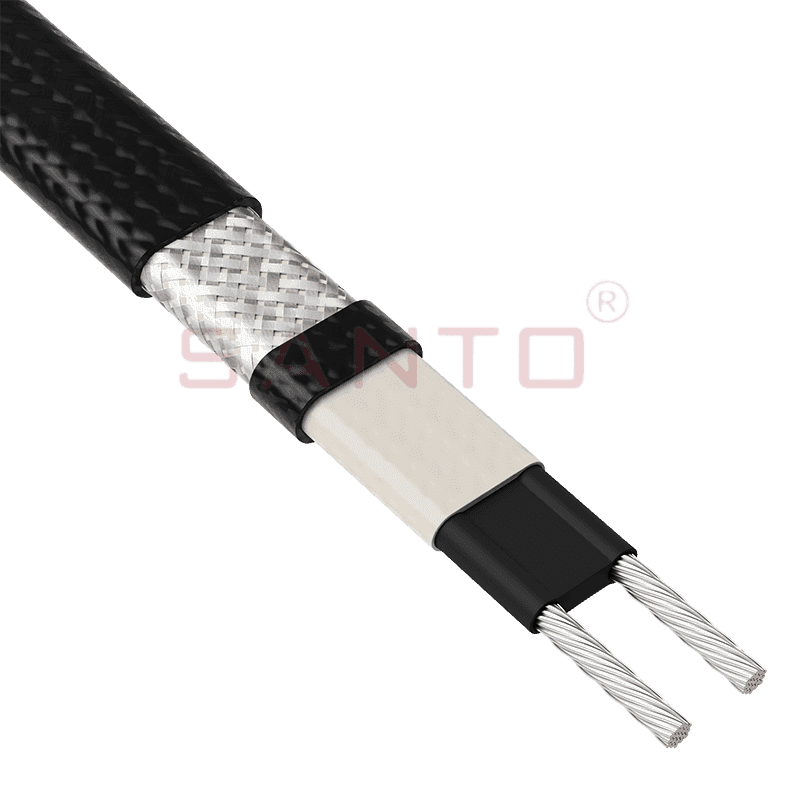
The SANTO UFA range of self-regulating heating cables is mainly used for frost protection of pipes and vessels but can also be used to maintain processes up to 65°C. These heating cables are available...
See Details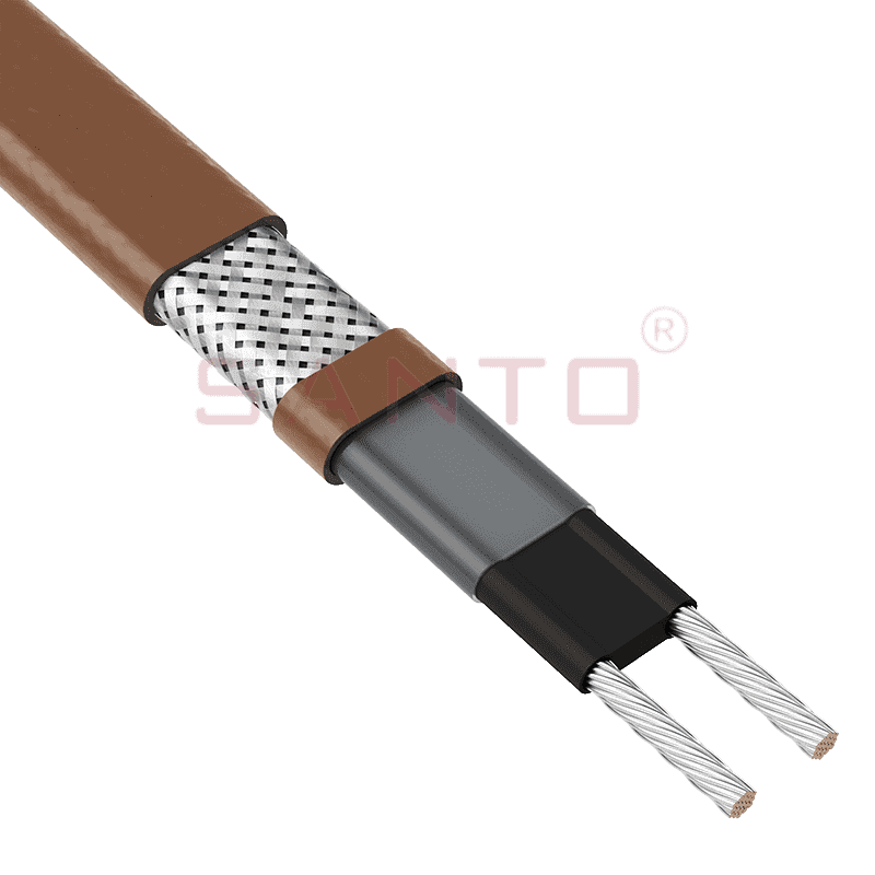
The SANTO UFB range of self-regulating heating cables is mainly used for frost protection of pipes and vessels requiring a higher power output than the UFA heating cables can supply. They can also be ...
See Details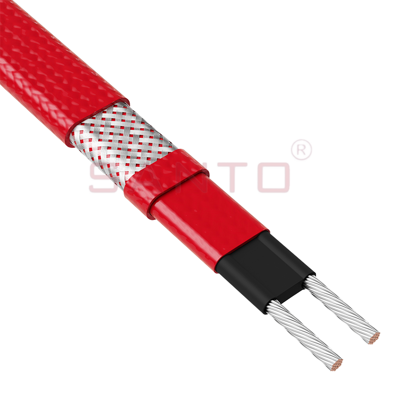
The SANTO UFC range of self-regulating heating cables is used for frost protection of pipes and vessels that require steam cleaning. They can also be used to maintain processes up to 121°C. These heat...
See Details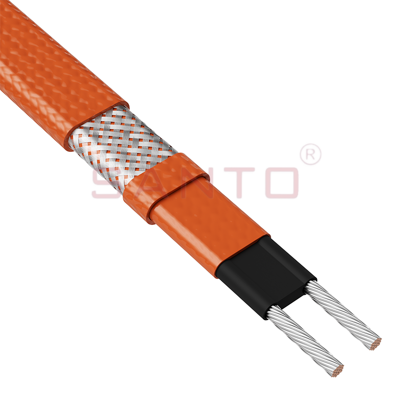
The SANTO UFO range of self-regulating heating cables is mainly used for frost protection of pipes and vessels that require steam cleaning . They can also be used to maintain processes up to 150°C. Th...
See Details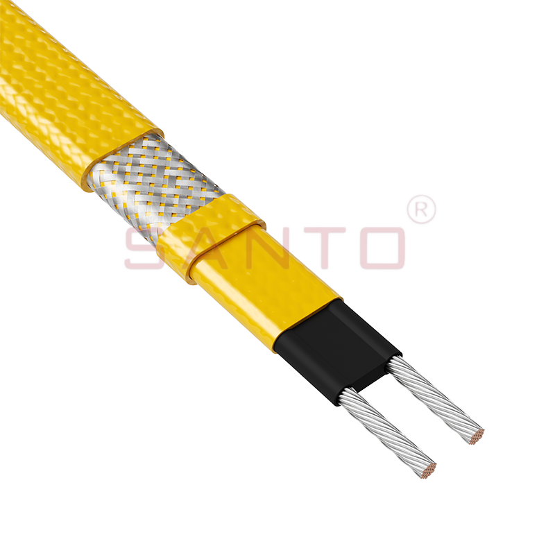
The SANTO UFD series of self-regulating heating cables are mainly used for freeze protection of pipes and vessels, but can also be used to maintain processes up to 200°C. These heating cables are avai...
See Details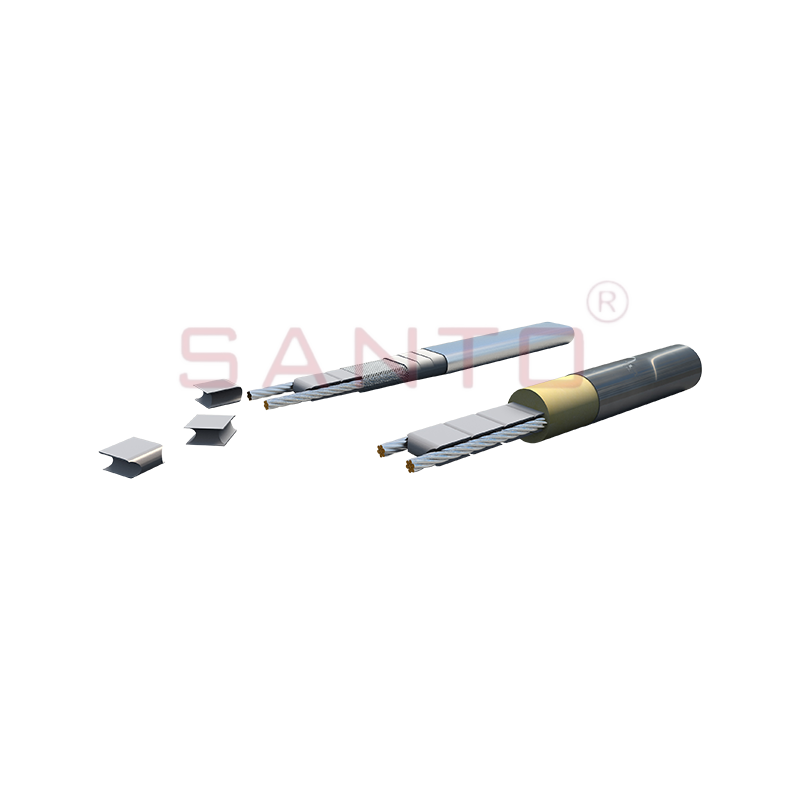
SANTO UFY heating wire is suitable for applications that maintain process temperatures up to 260 ℃ and can be steam blown; The self-regulating and parallel circuit heating wires of the UFY series are ...
See Details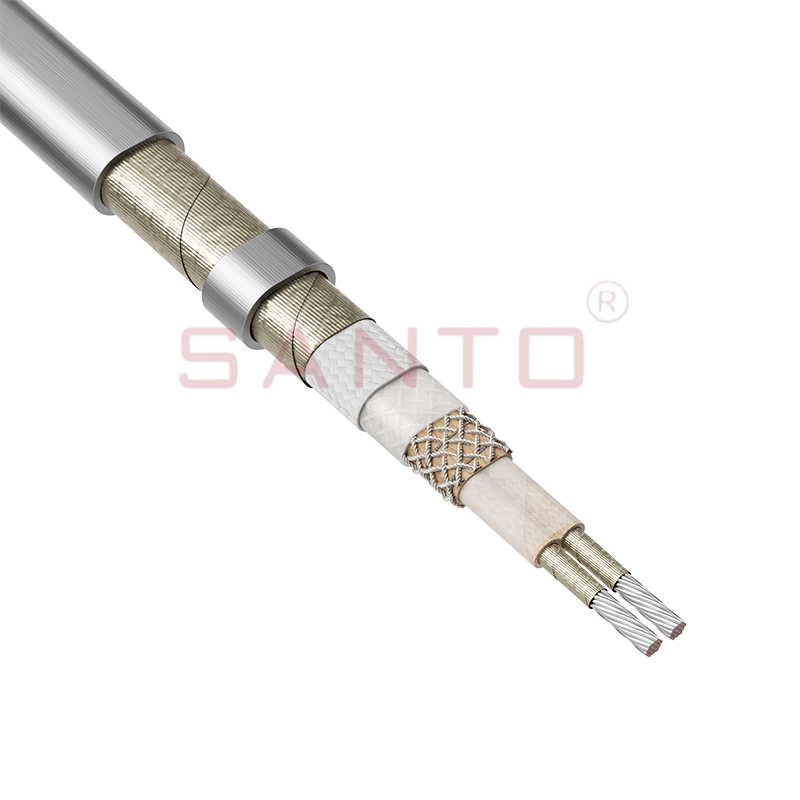
The SANTO UFM series self-regulating heating cables are mainly used for freeze protection of pipes and vessels, but can also be used to maintain processes up to 400°C. These heating cables are availab...
See Details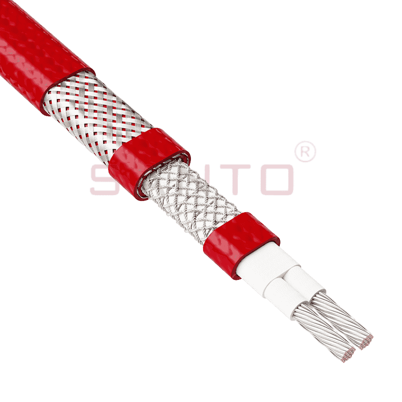
The SANTO ACC range of power-limiting heating cables is mainly used for temperature maintenance of processes and offers the advantage of a high power output at high temperatures which can reduce the n...
See Details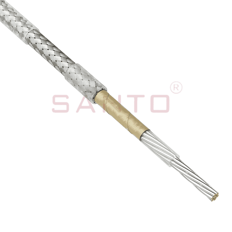
The stranded high temperature conductor is nickel plated to ensure a long life at elevated temperatures in corrosive environments. It is electrically isolated using an innovative sandwich construction...
See Details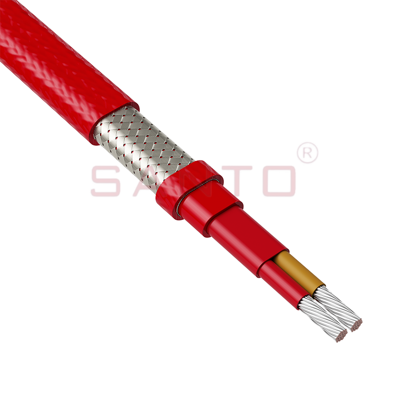
The stranded high temperature conductor is nickel plated to ensure a long life at elevated temperatures in corrosive environments. It is electrically isolated using an innovative sandwich construction...
See Details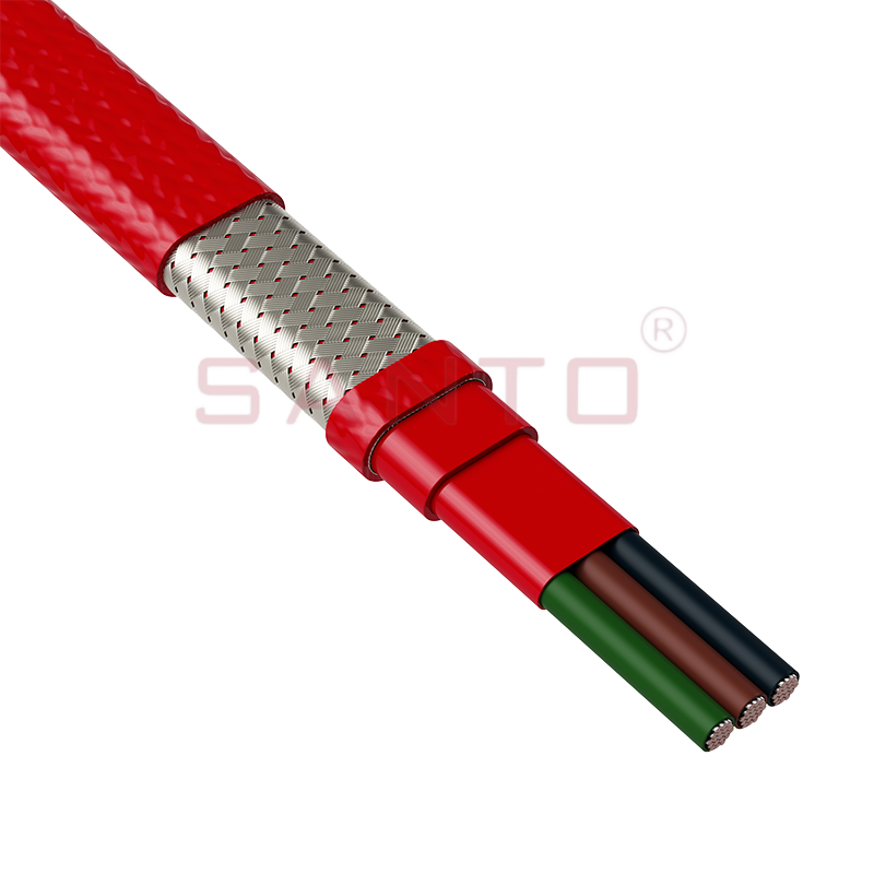
The stranded high temperature conductor is nickel plated to ensure a long life at elevated temperatures in corrosive environments. It is electrically isolated using an innovative sandwich construction...
See Details
SANTO HAx mineral insulated (MI) Alloy 825 series heating cables are suitable for use in hazardous areas. They have been designed for use in freeze protection and temperature maintenance applications ...
See DetailsSanto electric heating strips are widely used in key industries in China.

